Tuesday, 19 November 2013

New ATV 5 Watt Class-A amplifier

Last week Erwin, PE2ER, informed me that he had an assembly kit of a 23 cm amplifier. Since I am involved with some ATV activities these days, he asked me if I could use this kit. I struggled with some PA designs last weeks ( with power modules or CLY15) and therefore I was very glad with this offer. 
Last sunday I assembled the 1.2 GHz amplifier which is a design of PA0VRE from 2002.
It contains two SHF transistors: A BFQ68 and a BFQ136. The amplifier is able to generate 5 Watts RF power at 1.2 GHz with 200 mW input.
Assembling the kit was a delicate job. Some very small SMDs (2p2) had to find their way to the pcb and the whole circuit is mounted on a heatsink. 
All details are here: http://www.van-rees.nl/23pa/versieNL.PDF

Anyway, after building the first test on the bench were promising.


                                             The 23 cm amplifier finished

This morning I connected the amplifier to the ATV baseband circuit, connected the biquad antenna to the amp and pointed the antenna to the local ATV repeater and switched the power on.
A nice steady ATV signal at 10 GHz from PI6ZTM came back for me:

                  
    My 1255 MHz ATV signal (LH upper corner) arrived at the PI6ZTM repeater


 LNB for 10 GHz reception and dual quad antenna for 23 cm transmissions. With this    antenna setup a distance of 4.2 km between my QTH (JO22gb) and the repeater on "De Blankaard" (JO22fb) is bridged.


Steady ATV FM signal

I am curious what is possible with the 1.2 GHz Watts available now. Maybe, now it is also time to give my ATV antenna a permanent place on the roof.
Thanks Erwin !


Sunday, 10 November 2013

40 MHz DDS Generator

Last Friday the DDS AD9850 module arrived from China.

                                      The $ 5 AD9850 DDS module has arrived..

Time to unite the module with the rest of the circuit which I had prepared already according to the design of VK5TM: http://www.vk5tm.com/homebrew/dds/dds.php
See also my blog posting of October 25 showing how the control circuitry with 16F628A PIC and display has been designed.


Test set-up. The generator provides a 7380 KHz signal which is monitored by the frequency counter in the back. It was verfied that the generator upper frequency is 40 MHz.


I added a small seperate power supply circuit with a LM317T to provide a 3.3 Vdc voltage for the DDS module. The module is located on the right upper side of the housing.

The sine output of the DDS module is fed to a filter circuit with a cutoff frequency of appr. 60 MHz. 

A 1 transistor output stage with 2N3904 provides some gain.
                                                      1 stage transistor amplifier


Below you see the output of the DDS Generator on my scope. This looks like a real sine form don't you think so?  In this case a 17.460 MHz signal was applied. 6 divisions times 0.4 Volts makes a signal amplitude of 2.4 Volts peak-peak. At the end of the range (40 MHz) the amplitude drops to about 1.6 Volts peak-peak


Anyway, I think we are spoilt these days with nice electronics like this 40 MHz DDS module for sale for under $ 5...


Tuesday, 5 November 2013

First SSB QSO on 28 MHz with Iceland

This weekend, to my surprise, I was able to make a nice SSB QSO with Iceland with only 20 Watts. Odinn, TF2MSN, responded on my call on 28.490 MHz. I have made previous contacts with Iceland on 10m, but all are in digimode.
Odinn, who lives on the west side of Iceland in Akranes, has a nice QSL-design:


The QSO was was confirmed by eQSL:


Since conditions this weekend on 28 MHz were fine, I diverted to 24 MHz, one of the WARC bands,  to add some contacts on this band. This trial on November 3 was quite succesful:

24.980 MHz - SSB qso with LZ1GU
24.950 MHz - SSB qso with SV2DSJ/p (SOTA event)
24.912 MHz - CW with SX1DX
24.920 MHz - PSK63 with EB5DZC
24.920 MHz - PSK31 with RN5AA
24.920 MHz - PSK31 with EA7ZY


          Mikhail , RN5AA, from Moscow sent me this fb eQSL of a 24 MHz digimode QSO


Friday, 1 November 2013

G5RV junior antenna survived last storm


For more than 5 years, for HF communications I use the  G5RV Junior antenna covering the  10, 15, 17, 20, 30 and 40 meter ham bands.  It has 2 radiators of 7.75 m length each connected  to a  450 ohm ladder line. Termination is an SO-239 jack to connect to the RG58 50 ohms coaxial cable running to the rig. This antenna can be erected in a dipole or inverted V configuration. I choose the inverted V option. One radiator runs over the rooftop of my house and the other radiator runs above my garden.  The antenna  can handle up to 1500 watts (Allthough I normally run not more than appr. 20 Watts RF)


The G5RV junior antenna is a derivative from the G5RV which was originally designed to work on 20m with 4 to 6 low angle lobes reaching out in all directions.

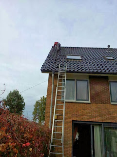
I use the antenna  in combination with an antenna tuner connected to the Yaesu FT-450 and have made hundreds of QSO’s with this aerial. It has survived many hi winds including last storm of Monday October 28  (up till windforce 10 in Zoetermeer) which blew away three of my tiles.

Replacement of tiles after the storm. Part of the G5RV jr antenna can be seen on the lefthand side