Sunday, 29 December 2013

HDR photography

Although not directly related to the radio hobby this part of the photo hobby might be interesting for you as well.

Yesterday we went to an area called Noord-Aa in Zoetermeer. I gathered some photoos with my Canon EOS1000D camera. Used a tripod for proper stabilization. The photoos I took, were a mix of overexposed, underexposed and normal exposed recordings, serving as building blocks for my first HDR pictures.

Joachim Seibert, PA1GSJ, reported on his new blog about HDR  (High Dynamic Range) photography:
http://recordingphotons.blogspot.nl/2013/12/handheld-hdr-photography.html

I used the freeware program "Picturenaut3.2". This program allows you to upload a number of pictures and merge them into one picture with more/different details.

These are my first "acceptable" results:


Thursday, 26 December 2013

24 VDC switching power supply

While cleaning up my attic I found this module. Reading the label revealed that it is a switching power supply, capable of delivering 24Vdc @ 2.5 Amps.
Nice design; it is very small (appr. 10 x 5 cm) so it can be incorporated into existing designs. Have to think of an application for this 60 Watts toy.

Saturday, 21 December 2013

Double duplex QSO

Yesterday I had a remarkable QSO with Hans, PE1DWA.
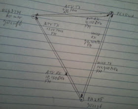
We had set up a duplex ATV connection and a duplex voice connection.
For ATV we used the repeater frequencies of PI6ZTM (10,150 GHz out, 1255 MHz and 433 MHz in).
For voice 2 meter and 4 meter band were used: 144.750 MHz and 70.450 MHz.
So in total we used 5 different frequencies. At least remarkable.
I made a map this event:


Except for the ATV transmission on 70cm (which was in AM, one suppressed sideband) all transmissions were in FM.

Tuesday, 17 December 2013

> 10k pageviews

Today the number of pageviews exceeded 10,000.
Thanks visitors and readers of this blog !
Happy Xmas and new year for all of you.


Sunday, 15 December 2013

1.2 GHz biquad antenna ready

Today I finished the biquad antenna. It is a lightweight version of another biquad I used before. This evening I fixed the antenna onto roof. 
Opening the attic window to stick the antenna outside is not necessary anymore which is good since winter temperatures are approaching.


             Here you see the antenna with a bunch of RG6/U coaxial cable (10 meters)


                                                         This is how I started


To make the antenna moisture proof a transparant box was glued over the element

Antennas on the roof. In front LNB for 10 GHz RX in the back the 23 cm biquad for TX

The antenna is connected to the ATV transmitter via 10 meters of coaxial cable. I intended to buy hi frequency low loss 50 ohms coax like H100 or Aeroflex. But the prices of this type is rather high. About 4 euro's each meter. In the "Praxis" they sell RG6/U  75 ohms coaxial cable for regular satellite receiver use. A bunch of 10 meters sells for 10 euro's. I thought the difference between 50 and 75 ohms is not that much (SWR of 1:1.5 and reflected power is only 4%). This appeared to be true. My ATV signal is copied in good quality by the repeater. The specifications show that the attenuation of 10 meters RG6/U is approximately 2.5 dB at 1.2 gigahertz . Not that bad.

You can find the dimensions of the antenna in my blog article of September 2013.

Tuesday, 19 November 2013

New ATV 5 Watt Class-A amplifier

Last week Erwin, PE2ER, informed me that he had an assembly kit of a 23 cm amplifier. Since I am involved with some ATV activities these days, he asked me if I could use this kit. I struggled with some PA designs last weeks ( with power modules or CLY15) and therefore I was very glad with this offer. 
Last sunday I assembled the 1.2 GHz amplifier which is a design of PA0VRE from 2002.
It contains two SHF transistors: A BFQ68 and a BFQ136. The amplifier is able to generate 5 Watts RF power at 1.2 GHz with 200 mW input.
Assembling the kit was a delicate job. Some very small SMDs (2p2) had to find their way to the pcb and the whole circuit is mounted on a heatsink. 
All details are here: http://www.van-rees.nl/23pa/versieNL.PDF

Anyway, after building the first test on the bench were promising.


                                             The 23 cm amplifier finished

This morning I connected the amplifier to the ATV baseband circuit, connected the biquad antenna to the amp and pointed the antenna to the local ATV repeater and switched the power on.
A nice steady ATV signal at 10 GHz from PI6ZTM came back for me:

                  
    My 1255 MHz ATV signal (LH upper corner) arrived at the PI6ZTM repeater


 LNB for 10 GHz reception and dual quad antenna for 23 cm transmissions. With this    antenna setup a distance of 4.2 km between my QTH (JO22gb) and the repeater on "De Blankaard" (JO22fb) is bridged.


Steady ATV FM signal

I am curious what is possible with the 1.2 GHz Watts available now. Maybe, now it is also time to give my ATV antenna a permanent place on the roof.
Thanks Erwin !


Sunday, 10 November 2013

40 MHz DDS Generator

Last Friday the DDS AD9850 module arrived from China.

                                      The $ 5 AD9850 DDS module has arrived..

Time to unite the module with the rest of the circuit which I had prepared already according to the design of VK5TM: http://www.vk5tm.com/homebrew/dds/dds.php
See also my blog posting of October 25 showing how the control circuitry with 16F628A PIC and display has been designed.


Test set-up. The generator provides a 7380 KHz signal which is monitored by the frequency counter in the back. It was verfied that the generator upper frequency is 40 MHz.


I added a small seperate power supply circuit with a LM317T to provide a 3.3 Vdc voltage for the DDS module. The module is located on the right upper side of the housing.

The sine output of the DDS module is fed to a filter circuit with a cutoff frequency of appr. 60 MHz. 

A 1 transistor output stage with 2N3904 provides some gain.
                                                      1 stage transistor amplifier


Below you see the output of the DDS Generator on my scope. This looks like a real sine form don't you think so?  In this case a 17.460 MHz signal was applied. 6 divisions times 0.4 Volts makes a signal amplitude of 2.4 Volts peak-peak. At the end of the range (40 MHz) the amplitude drops to about 1.6 Volts peak-peak


Anyway, I think we are spoilt these days with nice electronics like this 40 MHz DDS module for sale for under $ 5...


Tuesday, 5 November 2013

First SSB QSO on 28 MHz with Iceland

This weekend, to my surprise, I was able to make a nice SSB QSO with Iceland with only 20 Watts. Odinn, TF2MSN, responded on my call on 28.490 MHz. I have made previous contacts with Iceland on 10m, but all are in digimode.
Odinn, who lives on the west side of Iceland in Akranes, has a nice QSL-design:


The QSO was was confirmed by eQSL:


Since conditions this weekend on 28 MHz were fine, I diverted to 24 MHz, one of the WARC bands,  to add some contacts on this band. This trial on November 3 was quite succesful:

24.980 MHz - SSB qso with LZ1GU
24.950 MHz - SSB qso with SV2DSJ/p (SOTA event)
24.912 MHz - CW with SX1DX
24.920 MHz - PSK63 with EB5DZC
24.920 MHz - PSK31 with RN5AA
24.920 MHz - PSK31 with EA7ZY


          Mikhail , RN5AA, from Moscow sent me this fb eQSL of a 24 MHz digimode QSO


Friday, 1 November 2013

G5RV junior antenna survived last storm


For more than 5 years, for HF communications I use the  G5RV Junior antenna covering the  10, 15, 17, 20, 30 and 40 meter ham bands.  It has 2 radiators of 7.75 m length each connected  to a  450 ohm ladder line. Termination is an SO-239 jack to connect to the RG58 50 ohms coaxial cable running to the rig. This antenna can be erected in a dipole or inverted V configuration. I choose the inverted V option. One radiator runs over the rooftop of my house and the other radiator runs above my garden.  The antenna  can handle up to 1500 watts (Allthough I normally run not more than appr. 20 Watts RF)


The G5RV junior antenna is a derivative from the G5RV which was originally designed to work on 20m with 4 to 6 low angle lobes reaching out in all directions.

I use the antenna  in combination with an antenna tuner connected to the Yaesu FT-450 and have made hundreds of QSO’s with this aerial. It has survived many hi winds including last storm of Monday October 28  (up till windforce 10 in Zoetermeer) which blew away three of my tiles.

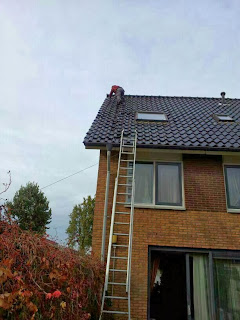
Replacement of tiles after the storm. Part of the G5RV jr antenna can be seen on the lefthand side

Friday, 25 October 2013

AD9850, a Direct Digital Synthesizer IC

If you search on eBay for AD9850 you will find a lot of modules equipped with this nice DDS (Direct Digital Synthesizer) IC. Most of those modules incorporate a 125 MHz Xtal oscillator. The modules are offered often for less than $5.
With this module you are able to build your own sine/square wave generator
that runs from 1 Hz till 40 MHz in steps of 1 Hz.


There is some control required. Homebuilders often use a PIC (for example 16F628A).

VK5TM describes some AD9850 generators on his website. Here you will also find the
required hex files for PIC programming:


http://www.vk5tm.com/homebrew/dds/dds.php


Some specifications for the AD9850 chip:

The AD9850 is a highly integrated device that uses advanced DDS technology coupled with an internal high speed, high performance, D/A converter and comparator, to form a complete digitally programmable frequency synthesizer and clock generator function.
When referenced to an accurate clock source, the AD9850 generates a spectrally pure, frequency/ phase-programmable, analog output sine wave.

FEATURES and BENEFITS

    125 MHz Clock Rate
    On-Chip High Performance DAC and High Speed Comparator
    DAC SFDR > 50 dB @ 40 MHz AOUT
    32-Bit Frequency Tuning Word
    Simplified Control Interface: Parallel Byte or Serial Loading Format
    Phase Modulation Capability

    3.3 V or 5 V Single-Supply Operation
    Low Power: 380 mW @ 125 MHz (5 V)
    155 mW @ 100 MHz (3.3 V)
    Power-Down Function
    Ultrasmall 28-Lead SSOP Packaging


Friday, 18 October 2013

Worked All Continents Award

Doesn't that sound great ? "Worked All Continents". 
It is not that difficult to get this certificate on your "Wall of Fame". You only have to make 6 QSO's.


In  Oct. 2006 I applied for the basic WAC-certificate (mixed mode) with following contacts:

North America : W1ZS (14 MHz, PSK31)
South America : YV5AAX (14 MHz, PSK31)
Oceania : YB0JIV (14 MHz, PSK31)
Asia: RV9WP (14 MHz, SSB)'
Europe: SP6GOX (14 MHz, SSB)
Africa: EA8OI (7 MHz, SSB)


                                                  WAC on my "Wall of Fame"


Allthough I am not an award hunter, this award I treasure.

Here you can read everything about the WAC award and the application:

http://www.iaru.org/worked-all-continents-award.html


Saturday, 12 October 2013

50 MHz SSB QSO confirmation from Bretagne

Since I do not have the proper outdoor antenna to work on the 6 m band I am not often "radio active" in this part of the radiospectrum. During sporadic E openings in the spring/summer however I sometimes divert to 50 MHz and use an improvised aerial (like an in-house dipole). Apparantly, 24 June 2009, more than 4 years ago, was such a day with Es openings. Today I received the eQSL from Alain, F6HRP from Bretagne, Cotes d'Armer (IN88kn) from the SSB QSO made that day.

A nice begin of the free saturday !

                                           eQSL F6HRP, 24 June 2009

Thursday, 10 October 2013

BFG591, ATV amplifier for 1.2 GHz

Some blog entries ago I informed you about my intention to build a 1.2 GHz amplifier with a CLY15 RF mosfet. I ordered 3 of them and did extensive trials. But in the end I had to conclude these devices are to delicate for me. I demolished 2 of them in 5 minutes time and the third provided almost no RF power in my circuit. 
I decided to look for another semiconductor that could help me in the GHz range. Hans, PE1DWA, informed me that a bi-polar transistor, the BFG591 could be interesting. This semiconductor has an Ft of 7 GHz and at 23cm I should easily be able to get 500 mW RF from it. I ordered 5 of them at eBay for about 4 euros.
Yesterday I built this circuit:


                                500 mW 1.2 GHz amplifier with BFG591

Although I have no device to measure the power at this rather high frequency I think half a Watt is a fair estimate that the circuit is producing.
With a bi-quad antenna I could get my signal to the local ATV repeater PI6ZTM. It was verified that the videosignal that came from a DVD-player  arrived at the local repeater. Although signal strength is not high enough to get a clear picture I recognized the transmitted pictures, and they were even in color.


  PI6ZTM repeater picture; in the left hand upper corner my video signal at 1255 MHz

                                          Snapshot of the 1.2 GHz  \  500mW amplifier

This is a good step forwards. In the mean time I ordered an MRF284 which is able to provide 5 Watts at 1255 MHz. Another 3 weeks to wait until it arrives from China...

Note: As you can see, I drawed the circuit by hand. Although I have computer programs to generate a drawing I did it in the old-fashioned way: Pencil & paper. Including scanning this takes me about 10 minutes time. A computer drawing consumes in most cases more than half an hour.


Sunday, 6 October 2013

Nice QSO with Sahara

This afternoon I was lucky to find Mohamed, 7X3FG on 28 MHz band in PSK31 mode.
The signal from Mohamed was strong in Holland. My 20 Watt signal on 28.120 MHz was received in good shape as well in Adrar, Algeria in the Sahara desert
Mohamed shows nice pictures of his QTH in Adrar, Algeria in the Sahara on www.qrz.com .
Have a look yourself.

 http://www.qrz.com/db/7X3FG


Thursday, 3 October 2013

Medium Wave tube receiver

Some time ago, one of the members of the Zoetermeer local radioclub, Mans PA2GHJ showed a homemade tube receiver. 

I think it is good, that in spite of the availability of all type of new components these days like PICs, Si570, Atmel chips and so on, there are still radio fans who use the old valve technology.

The receiver is a design with one tube (EF80) and  was designed for receiving AM stations in the medium wave broadcast band. The circuit contains a surprise: The anode voltage applied is only 6 Volts DC. In spite of this low supply voltage the receiver is quite sensitive. Under normal circumstances at least 15 stations can be heard through the headphones.

Here some nice pictures including the circuit diagram:
MW radio with battery and headphones, design by PA2GHJ


Side view also showing Amroh 402 coil


Circuit diagram 1 valve receiver

Sunday, 29 September 2013

Aircraft reflections on 4m

When analyzing WSPR signals in the 4 m band, signals can be spotted that are near the carrier wave of WSPR signals transmitted by other stations. These "ghost signals" are caused by aircraft reflecting the WSPR signal. Because the aircraft are moving a dopplershift is introduced.
This morning I caught a WSPR signal from PA0TBR on 70.0926 MHz with an aircraft reflection. I used the nice program SpecLab to have a close look at the signals:


The dopplershift between the carrier and the signal on the right (coming from the aircraft) is approximately 50 Hz. With this you can calculate the speed of the aircraft:

v= 50 * ((300/70.0926)/2) = 107 m/s = 385 km/h


Above you see a screenshot of WSPR March 2012. Measured dopplershift here was about 90 Hz which represents an aircraft speed of 695 km/h. A normal speed for an airliner jet at cruizing altitude.


More info: 

http://www.qsl.net/g3cwi/doppler.htm

http://www.pi4raz.nl/index.php?option=com_content&task=view&id=2792&Itemid=43

Friday, 27 September 2013

Australia on 28 MHz

This morning there appeared to be a very good radio path on 28 MHz between Europe and Australia. As you can see below, many WSPR signals from Europe reached VK5EI in the south of Australia, Adelaide:


                                 WSPR activity on 28 MHz, morning September 27, 2013

I was lucky to be one of the European stations who achieved to reach Joe, VK5EI in Adelaide ("Adelheid", QTH locator PF95he); a surprising 15930 km with 5 Watts.

Would this have been sporadic E propagation or were F-layers involved in this multi-hop path ? I do not know.

                                       Adelaide (South-Australia), city of churches

Saturday morning September 28, results were even better:

VK7AB, Glenn from New Norfolk Tasmania appeared on my screen (17.058 km). For me a new distance record on 10 meter band. Also Rob, T6RH, from Kabul, Afghanistan and Richard VK6XT, Broomehill (14.428 km) showed that the propagation conditions were surprisingly good:


                                         Saturday morning 28 September, WSPR 28 MHz